Base Station
Overview

The basestation is responsible for receiving, storing, and displaying map data as the robot explores. As shown in the block diagram above, the base station consists of an nRF24L01+ wireless transciever, an Arduino, an FPGA, a DAC, and a VGA resistor DAC.
Serial Configuration Device
In order to improve our setup time for the competition, we burned our Verilog onto the serial configuration device on the DE0-Nano board so that our program is loaded onto the FPGA at powerup. This way, we don’t need to program the FPGA every time we power up the FPGA. We did this by following the section in the DE0-Nano’s Appendix pertaining to the serial configuration device.
Verilog
Our Verilog code is split up into three main modules: a MAZE_MAPPER module, an SPI_SLAVE module, and an AUDIO module.
The SPI_SLAVE module recieves data from the Arduino by reading the SPI channel. It begins listening when the chip select (CS) line is asserted low, and clocks data on the MOSI line every time SCK has a rising edge.
The MAZE_MAPPER module takes input from the SPI_SLAVE module and provides color data to the provided vga driver module to draw elements on the maze. It parses the incoming data based on the SPI protocol and displays data accordingly.
Finally, the AUDIO module plays a three tone tune while an enable signal is asserted.
SPI protocal
The SPI protocol is identical to the RF protocol, for simplicity. Each tile is encoded in 16 bits, containing data about the x and y coordinates, positions of walls, IR treasure frequencies, and whether the tile has been visited before. The format that we use is shown below:
| 15-14 | 13-11 | 10-9 | 8-7 | 6-3 | 2 | 1 | 0 |
|---|---|---|---|---|---|---|---|
| X coord | Y coord | Treasure | 00 | Walls | Traversed? | Current Loc? | Finished? |
The top row of the above chart details which bits contain the data described by the row below it (starting with the first bit being named bit 0).
VGA Display
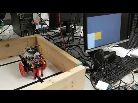
Our display represents the current state of the maze as observed by the robot. The display shows various elements of the maze as follows:
- White tiles are explored
- Gray tiles are unexplored
- The yellow tile represents the robot’s current location
- Walls are red
- Red, Green, and Blue boxes inside the tiles correspond to 7, 12, and 17 kHz treasures, respectively
- When done, a green bar appears on the right hand side
Here’s a small maze to illustrate many of these features:
Done Signal
When the robot completes its DFS algorithm, it transmits a message with a 1 in the least significant bit, signifying that the robot is done. When this is recieved the FPGA latches the done signal and displays a green stripe on the right side of the screen to signify that the robot is finished. When the done signal is received, a 1 is latched into a play_sound register, which both enables the audio module and displays the green bar.
Displaying the green bar involves a very simple if statement inside our draw loop:
if (PIXEL_X >= 10'd500 && PIXEL_X <= 10'd550) begin
  if (play_sound) COLOR_OUT = 8'b000_11_000;
end
In order to play the done sound, we separated the code out into an AUDIO module that would play a sound given an enable signal. The enable signal is directly driven by the same play_sound register to play the sound when the green bar is displayed:
AUDIO audio(
  .CLOCK_50(CLK),
  .ENABLE( play_sound ),
  .GPIO_1_D( GPIO_1_D ),
);