Nicholas Sarkis, Norman Chen, Eric Cole, Julia Currie, Divya Gupta, Wenhan Xia
Milestone 4: Putting it All Together
Introduction
The main goal of milestone 4 was to integrate all the previous labs and milestones into one seamless system. For this milestone, we were tasked with demonstrating that our robot can sucessfully communicate with the basestation and have it display walls and treasures as the robot finds them, and signal “done” on both the screen and the speakers when the robot has finished a maze. With the completion of this milestone, our robot and basestation will essentially be competition ready, and the rest of our time in lab will be spent making performance optimizations on the robot.
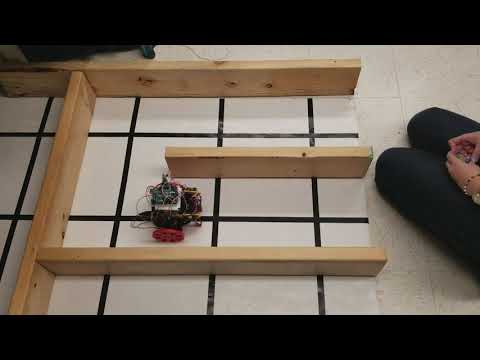
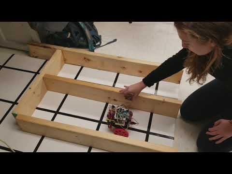
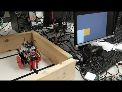
We were able to get the robot exploring a maze using a simple DFS algorithm and relaying its environment back to the base station. The base station correctly shows the robot’s current location, the walls and tiles its currently found, and any IR transmitters that is has come across. When the robot reaches all of the nodes that it can explore, it sends a done signal to the basestation, which then displays a green stripe on the screen and plays a three tone tune to signify that the robot is done.
FPGA Graphics
In order to complete this milestone, the base station needed to be updated to:
- Be able to displays walls on the top, bottom, left, and right of each tile
- Be able to show green, blue, or red markers on tiles that have treasures on them
- Be able to show a done signal on the screen
- Be able to play a done tone
Walls
In order to display walls on each tile, we can reference our protocol to figure out which walls to draw:
| 15-14 | 13-11 | 10-9 | 8-7 | 6-3 | 2 | 1 | 0 |
|---|---|---|---|---|---|---|---|
| X coord | Y coord | Treasure | 00 | Walls | Traversed? | Current Loc? | Finished? |
Bits 6-3 describe which walls a given tiles has. The bits are organized into the West, East, South, and North walls, in that order from bit 6 to bit 3. Once we have this information, drawing walls is easy! We just need to check to see if we’re within a spot inside a tile where a wall would be drawn, and if that tile has a wall in that place, we draw it.
Here’s an example of drawing the left (aka east) wall, and this pattern is repeated for each other direction:
if ( PIXEL_X <= tilex_pixel + `WALL_THICKNESS ) begin // left wall
  if ( grid_array[tiley][tilex] & (16'd1 << 6) ) begin
    COLOR_OUT = `COLOR_WALLS;
  end
end
Treasure
The treasure goal for this milestone was to be able to sense an IR treasure will driving on the maze, then send the result to the basestation to display the appropriate frequency on that tile on the VGA display. A treasure is represented by a small solid square in the middle of a tile: 7kHz is a red square, 12kHz is green, and 17kHz is blue. Up until now, we had assumed that the IR treausre could be placed anywhere on a wall and completely the milestone that way. Now that we know that the IR treasure will only be at intersections and 4cm from the ground, we will need to modify our mounting of the sensor and the code slightly. However, for this milestone we successfully implemented IR sensing of all 3 frequencies while traversing the maze using DFS. (see Lab2 writeup for IR circuitry, as it was not modified)
The FPGA implementation of the IR sensing is quite similar to the wall implementation. The treasure for a given tile is encoded in 2 bits, with 00 representing no trasure, 01 representing 7kHz, 10 for 12kHz, and finally, 11 for 17 kHz. Then, when we’re inside the center of the tile, we check to see which treasure the tile has, if any, and draw the appropriate color. Here’s the code we used to draw the IR markers seen in the above video:
if ( PIXEL_X >= tilex_pixel + `IR_BUFFER && PIXEL_X <= tilex_pixel + `TILE_SIZE - `IR_BUFFER ) begin
  if ( PIXEL_Y >= tiley_pixel + `IR_BUFFER && PIXEL_Y <= tiley_pixel + `TILE_SIZE - `IR_BUFFER  ) begin
    // In the draw zone for IR, choose color based on IR reading
    case ( (grid_array[tiley][tilex] >> 9 ) & 2'd3 )
      2'b01:   COLOR_OUT = `COLOR_7kHz;
      2'b10:   COLOR_OUT = `COLOR_12kHz;
      2'b11:   COLOR_OUT = `COLOR_17kHz;
      default: COLOR_OUT =  COLOR_OUT;
    endcase
  end
end
Done Signal
When the robot completes its DFS algorithm, it transmits a message with a 1 in the least significant bit, signifying that the robot is done. When this is recieved the FPGA latches the done signal and displays a green stripe on the right side of the screen to signify that the robot is finished. When the done signal is received, a 1 is latched into a play_sound register, which both enables the audio module and displays the green bar.
Displaying the green bar involves a very simple if statement inside our draw loop:
if (PIXEL_X >= 10'd500 && PIXEL_X <= 10'd550) begin
  if (play_sound) COLOR_OUT = 8'b000_11_000;
end
In order to play the done sound, we separated the code out into an AUDIO module that would play a sound given an enable signal. The enable signal is directly driven by the same play_sound register to play the sound when the green bar is displayed:
AUDIO audio(
  .CLOCK_50(CLK),
  .ENABLE( play_sound ),
  .GPIO_1_D( GPIO_1_D ),
);
Robot Arduino IR Sensing Code
We quickly learned that our fft code from the previous IR lab, broke our main robot’s code. After some debugging, we realized that putting the ADC into free running mode, broke all subsequent Analog_Read() calls which are essential for line following and wall sensing. We remedied this by only setting the ADC to free running mode and storing the old ADCSRA state when we enter the IR_poll funtion, so that we could restore it before we returned the value of the IR treasure we sensed. To sense and calculate the IR treasures, we sample 512 times, convert from ADC units, and then calculate the FFT using the fft library used in a previous lab. We then look at 3 FFT indices, one fore each frequency, and check to see if it is a above a threshold value. If it is we return 0-3 for the appropriate IR frequency.
char IR_poll(uint8_t sensor){

    old_ADCSRA = ADCSRA; //store old ADCSRA state
    ADCSRA = 0xe5; // set ADC to free running mode
    ADMUX = 0x44; // use adc4 with mux

    amux_select(sensor); //select which IR sensor from MUX input
    delayMicroseconds(10);

    cli();  // UDRE interrupt slows this way down on arduino1.0

    for (int i = 0 ; i < 512 ; i += 2) { // save 256 samples
      while(!(ADCSRA & 0x10)); // wait for adc to be ready
      ADCSRA = 0xf5; // restart adc
      byte m = ADCL; // fetch adc data
      byte j = ADCH;
      int k = (j << 8) | m; // form into an int
      k -= 0x0200; // form into a signed int
      k <<= 6; // form into a 16b signed int
      fft_input[i] = k; // put real data into even bins
      fft_input[i+1] = 0; // set odd bins to 0
    }
    fft_window(); // window the data for better frequency response
    fft_reorder(); // reorder the data before doing the fft
    fft_run(); // process the data in the fft
    fft_mag_log(); // take the output of the fft

    sei();

    ADCSRA = old_ADCSRA; //set the ADC back into single sample
    //AnalogRead() will not work in free running mode

     if ( fft_log_out[47] > 120 )     //return 1 for 7kHz
      return 1;
    else if ( fft_log_out[81] > 110 ) //return 2 for 12kHz
      return 2;
    else if (fft_log_out[114] > 100 )
      return 3;                       //return 3 for 17kHz
    else return 0;                    //return 0 otherwise

}
Robot Arduino IR Transmitting Code
We currently call the IR_poll() function between sensing an intersection and the line following logic, every 250 ms. This was under the assumption that the IR sensor could be placed anywhere on the walls, but now that we know that the IR treasure will only be placed at intersections, this chunk of code will be moved into our intersection logic, rather than being polled at a specific time interval. Once we call IR_poll, we then add assign it to that tile by calling tile_set_ir(pos,ir). This takes appropriate frequency treasure and adds it to the current tile, indicated by pos, in the master tile array which keeps track of all the tiles in the maze. The updated 16 bit number associated with this tile will then be sent out by tile_transmit(xy_pair xy) once the robot reaches the next intersection.
if (/*!ir_flag &&*/ millis() - last_IR_time > 250){
    uint8_t ir = IR_poll(AMUX_TREASURE_1); // can poll the IR sensor on either side of the robot

    tile_set_ir(pos, ir);

    last_IR_time = millis();
    ir_flag = 1;
  }
Done Signal
A “done” signal was implemented to indicate that the maze searching was completed. According to our encoding in lab4, the last bit of the 16-bit input signal to the FPGA is set if the robot reaches the end of the maze. In our code, a register play_sound takes the input signal “DATA_IN” ‘s last bit value. Once the play_sound register is set, the three-frequency tune implemented in lab 3 is played, and a green bar is drawn on the screen to signal that the process is complete.
// Draw the done signal if done
if (PIXEL_X >= 10'd550 && PIXEL_X <= 10'd600) begin
 if (play_sound) COLOR_OUT = 8’b000_11_000;
 end
end

// Audio integration
AUDIO audio(
 .CLOCK_50(CLK),
 .ENABLE( play_sound ),
 .GPIO_1_D( GPIO_1_D ),
);
Radio Communication
As part of this milestone, our system had to be able to display walls and treasures on the basestation monitor in real time as the robot found them in the maze as well as a done signal when the robot indicates that the maze has been mapped. In order to achieve this, we had to integrate our RF code using the nRF24L01+ transceivers from Lab 4 into the code bases of both our robot and basestation. We simplified this integration by taking our Lab 4 code and modularizing it into functions wireless_setup, wireless_read, and wireless_send in a separate wireless1.ino file and then including the header file in our main code.
Robot
The robot needs to transmit information about its current position and information about walls and treasures in the maze to the basestation. As we determined in Lab 4, we only want the robot to send new data (and not all information about the entire maze) in order to conserve power. Therefore, we decided to only transmit to the basestation after every intersection and to send information about the most recently traversed tile.
To do this, we define a function called tile_transmit which sends information about the previous tile to the basestation using our 16-bit packet encoding.
void tile_transmit(xy_pair xy){
  uint16_t to_send = tile_array[xy.x][xy.y].data | mapper_done_flag | 1<< 2; // send data of most recently traversed tile including done flag
  wireless_send ( &to_send, sizeof( uint16_t ) );
}
We then call the tile_transmit function a set time after the robot has detected an intersection to send the previous tile’s information, stored in xy_pair prev_pos, and use a variable send_flag to only transmit once.
if (send_flag && (millis() - last_send_time > SEND_TIMER)) {
  send_flag = 0;
  tile_transmit(prev_pos);
}
We also call this function when maze-mapping is complete, and the robot has to send the done signal back to the basestation.
if (to_turn == 255) {
 mapper_done();
 tile_transmit( pos );
 while(1) {
   drive(LEFT_ZERO, RIGHT_ZERO);
 }
Additionally, we increased the RF power setting in wireless_setup to HIGH to reduce the risk of dropped packets.
// set the power
// RF24_PA_MIN=-18dBm, RF24_PA_LOW=-12dBm, RF24_PA_MED=-6dBM, and RF24_PA_HIGH=0dBm.
radio.setPALevel(RF24_PA_MIN);
Basestation
The basestation code remains relatively unchanged from lab 4.
We first need to initialize the maze with the correct x and y values. Because we output the entire maze to the fpga, we need to make sure that every tile is correctly initialized such that the fpga does not overdraw a tile.
  // Initialize maze
  for (int i = 0; i < X_SIZE; i++) {
    for (int j = 0; j < Y_SIZE; j++) {
      maze[i][j] = 0;
      maze[i][j] |= ((i&3) << 14) | ((j&7) << 11);
    }
  }
Now that the maze is initialized, we can now wait to receive some data from the robot.
 while (timeout)
  {
    // Wait until we get data or timeout
    timeout = wireless_read( &got_data, sizeof(uint16_t) );
  }
Once the above loop either gets some data or times out, we just transfer over SPI the entire maze updated with the new data we received.
if (got_data & 0x1) done = 1;

// First, stop listening so we can talk over SPI
radio.stopListening();

SPI.beginTransaction(SPISettings(1000000, MSBFIRST, SPI_MODE0)); //10MHz

unsigned char got_x = got_data >> 14;
unsigned char got_y = (got_data >> 11) & 7;
maze[got_x][got_y] = got_data;
for (uint16_t x = 0; x < X_SIZE; x++){
    for (uint16_t y = 0; y < Y_SIZE; y++){
        if (maze[x][y] == 0) continue;
        if ((x != got_x) || (y != got_y))
            // Clear the current? bit
            maze[x][y] = maze[x][y] & 0xfffd;
        else
            // Set the current? bit
            maze[x][y] = maze[x][y]  | 1 << 1;
        digitalWrite(7, LOW);
        delay(1);
        SPI.transfer16(maze[x][y] | done);
        digitalWrite(7, HIGH);
    }
}
Here’s a video of the robot completing a simple maze with radio communication!
Conclusion
This milestone was particularly challenging considering the combined code size of all our labs, and debugging was much more complicated since we were dealing with a much larger codebase than before. In the end, we were able to integrate all the labs and milestones throughout the semetester into one seamlessly working system. The next steps for us as a team is to continue to optimize both the design of the robot and the software in our system. In addition, we still need to integrate the microphone into the full system, as well as replacing our breadboard with the pcb we ordered. Here’s a video that demonstrates our robot traversing a simple maze and displaying walls, treasures, and a done signal.