Nicholas Sarkis, Norman Chen, Eric Cole, Julia Currie, Divya Gupta, Wenhan Xia
Milestone 3: Algorithms
Introduction
The main goal of milestone 3 was to implement a depth-first search (DFS) algorithm to facilitate maze exploration and to add an indicator to signal that the robot is done. Before we implemented the algorithm on our robot, we first ran a Matlab simulation to test the algorithm’s efficiency and robustness with different types of mazes. Once the simulation worked well, we translated the MATLAB code to C and added it to an Arduino program. The robot’s completion was indicated by a “Complete” message printed in the Matlab simulation, and by three lit LEDs for the real time maze mapping.
DFS: An Overview
Depth-first search (DFS) is an algorithm used for graph traversal that starts at a root node and explores as far as possible in one direction before backtracking and exploring other nodes. The general pseudocode for DFS is shown below. The frontier stack contains the list of nodes to visit, and current is the current node. A stack is used since it is a last-in-first-out (LIFO) data structure which facilitates proceeding as far in one direction before backtracking, or popping the stack.
frontier = new Stack();
frontier.push(root);

while (frontier not empty) {
    current = frontier.pop();
    foreach (n neighbor of current) {
        if (n not visited and not blocked) {
            frontier.push(n);
        }
    }
}
traversal_complete = 1;
In Simulation
Matlab DFS Algorithm
We implemented a simple DFS algorithm using Matlab for our maze simulation. In addition to our frontier stack, which we call ‘s’, we also define a second stack called ‘path’, which contains the list of nodes in the path taken through the maze. We require this second array to remember our path so that we can backtrack if all neighbors of the current tile are blocked by walls or have already been visited. Additionally, we define two arrays that have one-bit entries for every tile in the grid: the array visited tracks whether that tile has been visited or not, and the added array checks whether the tile has already been added to the frontier stack or not.
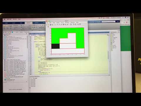
The commented Matlab code is shown below, as is a video of the simulation. The graphics functions are explained further in the next section. Tiles are marked as white if they are unexplored, green if they have been visited, and black if it is the current tile. After all explorable sections of the maze are explored, a “Complete” message is printed to the command window.
completed = 0; // 1 if maze has been fully explored
visited = zeros(6,6); // grid array, 1 if visited, 0 if not
added = zeros(6,6); // grid array, 1 if added to frontier, 0 if not
s = CStack(); // frontier stack
path = CStack(); // path stack

while (~completed)

  update_view( map, maze, wall_loc );
  s.push( [x,y] );
  while (~s.isempty())
      maze(x,y) = 0.5; // color current location green
      wall_bin = de2bi(wall_loc(x,y), 4, 'right-msb');

      // if all neighbors are visited or are blocked by walls, backtrack
      if ((wall_bin(1) == 1 || ((x-1 >= 1) && visited(x-1,y) == 1)) ...
        && (wall_bin(2) == 1 || ((x+1 <= 4) && visited(x+1,y) == 1)) ...
      	&& (wall_bin(3) == 1 || ((y+1 <= 5) && visited(x,y+1) == 1)) ...
        && (wall_bin(4) == 1 || ((y-1 >= 1) && visited(x,y-1) == 1)))
          current = path.pop();
      // otherwise, pop the next node from the frontier stack
      else
          current = s.pop();
          path.push(current);
      end

      // update current position on map
      x = current(1);
      y = current(2);
      maze(current(1),current(2)) = 0;
      update_view( map, maze, wall_loc );
      pause(0.5);

      // mark tile as visited if it hasn't been visited before
      if ( visited(x,y) == 1)
         disp('Visited');
      else
        visited(x,y) = 1;

        // add all neighbors to stack, in order N,S,E,W
        wall_bin = de2bi(wall_loc(x,y), 4, 'right-msb');
        if ( (x-1) >= 1 && (added(x-1, y) == 0) && wall_bin(1) == 0 && visited(x-1,y) == 0)
            s.push( [x-1,y] );
            added(x-1, y) = 1;
        end
        if ( (added(x+1, y) == 0) && wall_bin(2) == 0 && visited(x+1,y) == 0)
            s.push( [x+1,y] );
            added(x+1, y) = 1;
        end
        if ( (added(x, y+1) == 0) && wall_bin(3) == 0 && visited(x,y+1) == 0)
            s.push( [x,y+1] );
            added(x, y+1);
        end
        if ( (y-1) >= 1 &&(added(x, y-1) == 0) && wall_bin(4) == 0 && visited(x,y-1) == 0)
            s.push( [x,y-1] );
            added(x, y-1);
        end
      end
      end

  // if frontier node is empty, then graph is fully explored
  completed = 1;
  disp('Complete');
end
Matlab Graphics
To represent our maze graphically, we drew a 4x5 grid of rectangles and displayed it in a MATLAB figure. We encoded this grid as a 4x5 matrix maze, with the value of the matrix representing the status of that location: 1 for unvisited, .5 for visited, 0 for the robot’s current location. We then displayed the status of each grid by MATLAB’s colormap function and the following color coding, updating colors on each step in the DFS.
Our grid starts out with every location unvisited (every square is white, and the value in maze is 1). Whenever our robot leaves a square, we change that location’s value in maze to 0.5, and the new square our robot moves to is updated to 0. Then we redraw the maze based on the updated matrix with our redraw function:
function update_view( map, maze, wall_loc )
    colormap(map);
    imagesc(maze);
    caxis([0 1])
    draw_walls(wall_loc);

end
This function does the following:
1) Set the color map to be used by imagesc, using our color mapping matrix:
map = [...
   0, 0, 0  %%black for maze value == 0 (current location)
   0, 1, 0  %%green for maze value == .5 (visited)
   1, 1, 1]; %%white for maze value == 1 (unvisited)
2) Draw the colors according to our updated maze
3) Draw the walls
To encode wall locations, we also used a 4x5 grid, which we named wall_loc. For each square in the grid, we used a 4-bit binary sequence: a one indicates a wall present on a given side, with the bits ordered West, East, South, North. For instance, our top left corner might be 1001, indicating walls to the left and up. These 4-bit encodings were stored as decimal values in the 4x5 wall_loc matrix.
We displayed walls by drawing a red line at the border of each grid where a wall is encoded as described above, using the following function:
function draw_walls( wall_loc )
    [num_row, num_col] = size(wall_loc);

    % Draw all north walls on image
    for r = 1:num_row
        for c = 1:num_col
            wall_bin = de2bi(wall_loc(r,c), 4, 'right-msb');

            % Draw all walls
            if (wall_bin(1) == 1) % NORTH wall
                line([c-0.5,c+0.5],[r-0.5,r-0.5],'color','r','linewidth', 3);
            end
            if (wall_bin(2) == 1) % SOUTH wall
                line([c-0.5,c+0.5],[r+0.5,r+0.5],'color','r','linewidth', 3);
            end
            if (wall_bin(3) == 1) % EAST wall
                line([c+0.5,c+0.5],[r-0.5,r+0.5],'color','r','linewidth', 3);
            end
            if (wall_bin(4) == 1) % WEST wall
                line([c-0.5,c-0.5],[r-0.5,r+0.5],'color','r','linewidth', 3);
            end
        end
    end
end
On Maze:
Algorithm: DFS in C
Coordinate System
One of the major differences between our simulation and actual implementation is that the robot’s orientation changes as it moves through the maze. Therefore, we must be able to translate between the robot’s cardinal directions and the “true north” as seen by the DFS algorithm. In order to determine directions, we use a North, South, East, West cardinal direction system, the directions are encoded as follows:
| Direction | Encoding |
|---|---|
| North | 0 |
| East | 1 |
| South | 2 |
| West | 3 |
In order to convert between the robot’s cardinal system and the “true north” cardinal system, we can use modular arithmetic using the encodings used above. If we keep track of the robot’s orientation, then we can easily convert between the two systems:
dir_relative_to_truenorth = robot_orientation + dir_relative_to_robot (mod 4)
For example, if a robot see something to the West of it (3), and it is facing East (1), then the actual direction relative to true north is North (0) because 3 + 1 = 0 (mod 4). This also works in the reverse direction. We have used range checks and addition/subtraction to implement a less computationally expensive version of the mod (%) operator.
Mapper Function
We created a mapper.c file to handle all of the code that keeps track of the maze and decides which direction to turn. Each time the robot reaches an intersection, it calls the at_intersection() method, and passes in the current walls that it sees. mapper.c then stores these records internally. The method then returns which direction that the robot should turn based on a DFS algorithm, which is calculated based off the following pseudocode:
sense walls to the left, right, and front

add all non-blocked directions to missed_oppertunities stack

if surounded by walls || visited tiles:
  pop path stack and move along it
else
  pop off missed_oppertunities and go to target
  push new location to path stack

Find the orientation of the target relative to the robot

Update maze array
Turning states
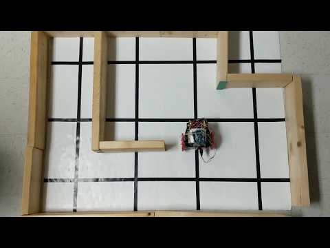
In order to get the robot to move according to our algorithm, we need to map each direction that at_intersection() can return to a direction that the board should move. If the robot receives NORTH, then the robot goes into the FOLLOW_LINE state, which essentially just keeps the robot driving straight. If the robot receives SOUTH, then the robot goes into the TURN_180 state, which rotates the wheels opposite to each other in order to turn the robot 180 degrees. If the robot receives WEST, then the robot will turn left, and EAST will cause the robot to turn right. Here’s a video of our robot moving according to our DFS algorithm.
Robot’s Done signal
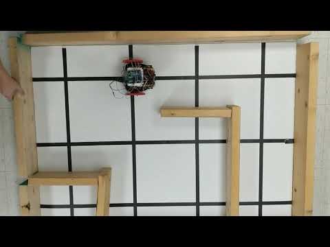
Our done signal is just lighting up three LEDs on our robot. This involves first adding a signal which at_intersection() can return to tell the robot that it is indeed done. We added a new state called DONE, which causes the robot to stop its wheels and light up the LEDs. Here’s a video of our robot completing a DFS!
Conclusion
By the end of this milestone we were able to simulate DFS maze exploration and fully implement DFS on our robot and signal when the maze is fully traversed. Looking ahead, we need still need to support the ending tone once the robot is done exploring and treasure identification in our robot’s implementation. We are also working on the layout for a PCB which should make our electronics more compact and reliable.
Work Distribution
All team members got exposure to all parts of the milestone tasks over the course of the two weeks. Nick, Julia, and Norman focused more on the real life algorithm, and Eric, Wenhan, and Divya focused more on the simulation.