Milestone 2
Introduction
The goal of this milestone is to add wall sensors to the robot and distinguish between 7, 12, and 17 kHz IR treasures.
Wall Detection
In order to navigate the maze, we need to periodically check for the presence of walls beside and in front of our robot. The first step in achieving this goal is to detect a single wall in front of the robot. We have chosen to use the short range IR sensors (part number GP2Y0A41SK0F) in order to detect walls around the robot. We began by first testing our sensor and using the following plot of output voltage and obstacle distance listed in the datasheet.

After testing the relationship based off this graph to convert the analog voltage read by the sensor into a distance in centimeters, we performed some calibration on our sensor by placing a wooden plank a known distance from the sensor and comparing what the Arduino read versus the actual distance. We discovered there was a small offset, but since it was fairly constant over the entire sensing range, we deemed it insignificant in the long run.
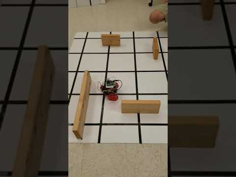
In conjunction with the TAs, we found the minimum distance between an intersection and a wall, which we used as a threshold for wall detection in our code. In order to demonstrate that our robot could actually sense walls, we programmed the robot to turn right at any intersection with a wall in front of it. The video of this code in use is below:
In the future, we also plan to implement left and right wall sensors to determine whether we can actually turn left or right. Unfortunately, the Arduino cannot accommodate more inputs, since the Arduino only has six analog input pins, and we already have nine input signals, including three for the wall sensors, four for the line sensors, one for the IR sensor, and one for the microphone. We will need to implement a CMOS multiplexer so that we can route various low-priority sensors to a single analog pin on the Arduino. This will allow us to follow a line, detect intersections, detect walls in front, to the left of, and to the right of our robot, detect IR beacons on both sides of our robot, and listen for a 660 Hz tone, all without any hardware changes.
Distinguishing 7, 12, and 17 kHz IR Signals
Last week, we showed that our optical circuit could distinguish between a 7 and 12 kHz signal output from the treasure board. We did this by establishing a simple threshold check for the bins corresponding to a 7 kHz and 12 kHz signal at our sampling rate, which were bins 47 and 81 respectively. To be able to distinguish a 17 kHz signal as well, all we had to do was add another condition to our code which checked the bin corresponding to a 17 kHz signal. We expected this to be bin 14 (17,000 Hz/ 148.4 Hz/bin = 14) and confirmed by checking the FFT output on the serial monitor.
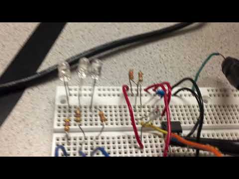
To demonstrate that our optical circuit could distinguish between the three different signals in a more visual way, we decided to add three different color LEDs, each corresponding a different signal frequency. When a treasure at that frequency is brought near the sensor, the corresponding LED turns on. We chose to pair the 7 kHz signal with the blue LED, the 12 kHz signal with the red LED, and the 17 kHz signal with the green LED. The updated code and our video demonstration are shown below.
/*
 adapted from OpenMusic's fft_adc_serial.pde
*/

#define LOG_OUT 1 // use the log output function
#define FFT_N 256 // set to 256 point fft

#include <FFT.h> // include the library

int LED1 = 13;
int LED2 = 8;
int LED3 = 7;

void setup() {
  Serial.begin(115200); // use the serial port
  TIMSK0 = 0; // turn off timer0 for lower jitter
  ADCSRA = 0xe5; // set the adc to free running mode
  ADMUX = 0x41; // use adc0 //40
  DIDR0 = 0x01; // turn off the digital input for adc0 //01
}

void loop() {
  while(1) { // reduces jitter

    cli();  // UDRE interrupt slows this way down on arduino1.0

    for (int i = 0 ; i < 512 ; i += 2) { // save 256 samples
      while(!(ADCSRA & 0x10)); // wait for adc to be ready
      ADCSRA = 0xf5; // restart adc
      byte m = ADCL; // fetch adc data
      byte j = ADCH;
      int k = (j << 8) | m; // form into an int
      k -= 0x0200; // form into a signed int
      k <<= 6; // form into a 16b signed int
      fft_input[i] = k; // put real data into even bins
      fft_input[i+1] = 0; // set odd bins to 0
    }
    fft_window(); // window the data for better frequency response
    fft_reorder(); // reorder the data before doing the fft
    fft_run(); // process the data in the fft
    fft_mag_log(); // take the output of the fft

    sei();

    Serial.println("start");
    /*for (byte i = 0 ; i < FFT_N/2 ; i++) {
      Serial.print(i);
      Serial.print(":");
      Serial.println(fft_log_out[i]); // send out the data
    } */
    delay(200);

    if ( fft_log_out[47] > 100 ){
      Serial.println("7kHz beacon dectected!");
      digitalWrite(LED1,HIGH);
      digitalWrite(LED2,LOW);
      digitalWrite(LED3,LOW);
    }
    else if ( fft_log_out[81] > 100 ){
      Serial.println("12kHz beacon dectected!");
      digitalWrite(LED1,LOW);
      digitalWrite(LED2,HIGH);
      digitalWrite(LED3,LOW);
    }
    else if (fft_log_out[114] > 95 ){
      Serial.println("17kHz beacon dectected!");
      digitalWrite(LED1,LOW);
      digitalWrite(LED2,LOW);
      digitalWrite(LED3,HIGH);
    }
    else{
      digitalWrite(LED1,LOW);
      digitalWrite(LED2,LOW);
      digitalWrite(LED3,LOW);
    }
  }
}
Conclusion
We were successful in our goal to add wall sensors to the robot and distinguish between 7, 12, and 17 kHz IR treasures. Looking forward, we will need to implement the CMOS multiplexer for our analog pins. We will also try to improve the range of our optical circuit, especially when detecting the 17 kHz treasure, possibly by increasing the gain of our amplifying circuit. Additionally, we plan to integrate our optical circuit on both the left and right sides of our robot for treasure detection on walls.