Milestone 1
Introduction
The main goal of this milestone is to prove the basic functionality of the robot, by proving that we can follow a line and navigate a figure eight on a grid.
Following a Line
Following a line was a fun challenge. In the end, we were able to follow both straight and reasonably curvy lines. If the curves were too harsh, our robot wouldn’t be able to react fast enough. We were able to solve that problem by decreasing the speed of our motors, but for the purposes of straight line following, faster is better so we sacrificed this functionality.
Hardware
We placed two line sensors right next to each other in the forward center of the chassis and two more sensors placed about 1.5cm farther out and about 1cm in front of the two center ones. We used this arrangment so that we would be able to continue line sensing while also being able to detect upcoming intersections in the grid. This layout also makes turning easier, because we are able to lock back onto the line much faster.
Code
Our main strategy for line following is to scale the motor speeds based on the relative darkness of the light sensor. In order to maximize speed, we run the motors at max speed, and subtract a value from one side’s motor if we need to realign on the black line.
The algorithm goes as follows:
// Initialize slowdown variables
int slowdown_left = 0, slowdown_right = 0;

// ... below this line is looped

// Update the line sensor values
line_left_value = analogRead(P_LINE_SENSOR_1);  // 0-1023
line_right_value = analogRead(P_LINE_SENSOR_2); // 0-1023

// Line following adjustments
if ( abs(line_left_value - line_right_value) < LIGHT_TOLERANCE ){
    // drive straight
    slowdown_left = slowdown_right = 0;
}else if (line_left_value > line_right_value){
    // turn left
    slowdown_left = map(line_left_value-line_right_value, 0, BLACK_VALUE-WHITE_VALUE, 0, 20);
    slowdown_right = 0;
}else if (line_left_value < line_right_value){
    // turn right
    slowdown_left = 0;
    slowdown_right = map(line_right_value-line_left_value, 0, BLACK_VALUE-WHITE_VALUE, 0, 20);
}
The above code uses the map() function to convert a different in line sensor readings to a motor slowdown value, so that the robot can adjust its position in realtime to follow the line while maintaining as close to max speed as possible.
Line Following Videos
Watch our robot follow both a straight line and a curvy line!
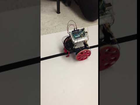
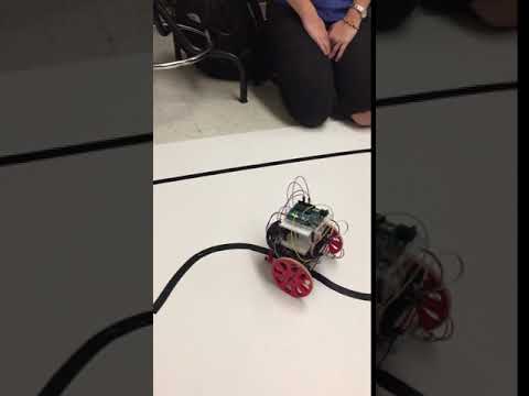
Our robot is a little shakey in these videos, beause the line sensor readings are being mapped to a large range of motor slowdown values. To make our line following smoother when following a grid, we tuned our mapping values to achieve a more gradual slowdown. You can see the improvement in our figure eight video below!
Traversing a Grid
Now that we can follow a line, it’s time to traverse a grid! We have two extra line sensors towards the edge of the robot to detect intersections. For each intersection we detect, the robot decides whether or not it wants to turn.
Code
In order to more accurately detect signals, we created a lightweight debouncing library that, while rudimentary, is enough for our purposes.
The functions are define in debounce.h:
// Call when a condition is true
void signal_condition(char debounce_var);

// Call when a condition is false
void clear_condition(char debounce_var);

// Check to see if the condition has been true
// for a consecutve [target] number of times
char poll_condition(char debounce_var, char target);
This allows us to avoid false positives when detecting intersections.
We tried many different ways of turning. Most of our active sensing turning methods were finicky and not very robust. So we opted for the less ideal but more suitable solution for this milestone: a fixed turning time. We turn for exactly 1.25 seconds, and then resume line following mode. This isn’t always perfect, but our line following algorithm is good enough to always get us back following the line. The general algorithm goes as follows:
loop
  mode: line follow?
    line following algorithm
    detect intersection?
      set mode: turn
  mode: turn
    spin one motor slower than the other
    has 1.25 seconds elapsed?
      set mode: line following
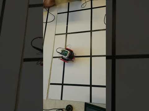
Figure Eight
Now that we can turn reliably, its time to do something cool with it! We managed to get our robot to do figure 8s for indefinentaly.
Code
In order to easily specify any turn pattern for our robot to follow, we have it lookup its next turn in an array, so that we can specify any combination of turns to make any pattern we want:
// Turns
#define LEFT                   0
#define RIGHT                  1
#define STRAIGHT               2

char figure_8[] = { RIGHT, LEFT, LEFT, LEFT, LEFT, RIGHT, RIGHT, RIGHT };
The code loops through this array to find the next move it should make when it detects an intersection.
Figure Eight Video
Conclusion
Our team was successful in our Milestone 1 goal to achieve line following and be able to navigate a figure eight on a grid. In the future, we may try to implement a more robust line following algorithm that doesn’t have to use a fixed turning time. We also want to increase our speed and might also try to incorporate PID feedback control principles into our algorithm to reduce jitter and reduce error.