Lab 4: Radio Communication and Map Drawing
Objective
The objective of this lab was to build off of the work we did in Lab 3 and draw a full maze on a VGA monitor while updating it in real time with information recieved from our robot. This information is transmitted through radio communication from our robot to our base station. We split into two groups, one which focused on implementing RF communication, and the other which further developed the FPGA implementation. Our two groups came together ultimately to merge our sections. In the end we were succesful in implementing a protocol for the robot to accurately communicate to the base station about the current state of the maze: robot’s current position, unexplored, and explored areas. The protocol also currently dicatates what bits are set aside for relaying walls, presence and frequency of treasures, and a done signal.
Radio Team:
Members: Nick, Eric, Julia
Materials:
- 2 Nordic nRF24L01+ transceivers
- 2 Arduino Unos
- 2 USB A/B cables
- 2 radio breakout boards with headers
Procedure
Sending information wirelessly between Arduino’s
First, we connected the radios to the special circuit boards, and plugged a radio into each of the two Arduinos with a supply voltage of 3.3V.

We downloaded the RF24 Arduino Libray and added it to our Arduino library directory. Next, we replaced the Getting Started code in the RF24 library with the “Getting Started” sketch from the course repository. In the Getting Started example code, we changed the identifier numbers to 0x000000002CLL and 0x000000002DLL using the handout formula: 2 ( 3D + N ) + X.
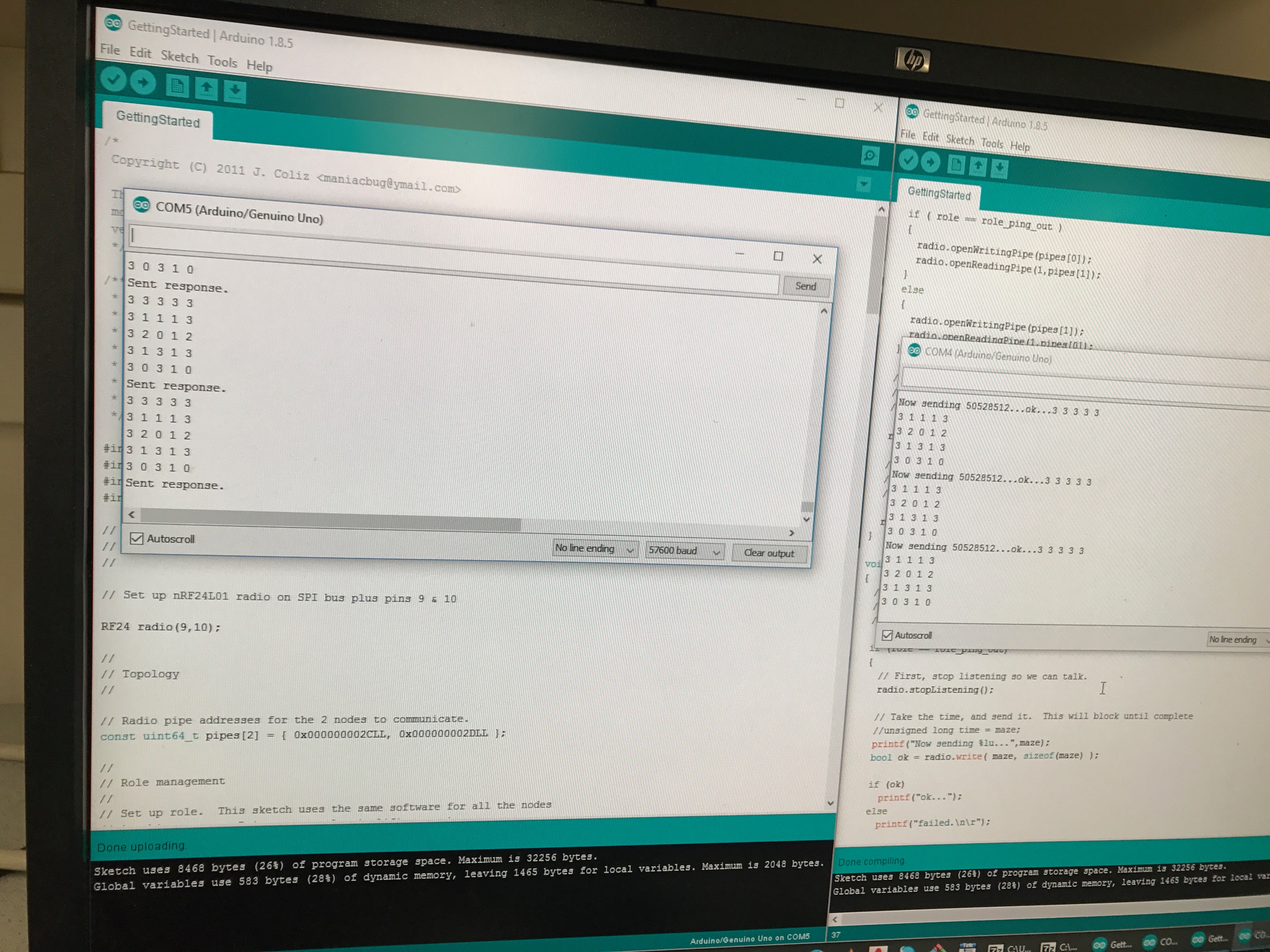
To test the radios, we connected both Arduinos to the lab computer and programmed the sketch to them. We chose one Arduino as transmitter, and typed “T” in its serial monitor. In the screenshot below, the left side serial monitor corresponds to the transmitter, and the right side serial monitor corresponds to the receiver. The signal sent by the transmitter was received by the receiver and sent back to the transmitter. The transmitter’s serial monitor also showed the round-trip delay.

Now that the wireless communication between the two Arduino was established, we increased the distance between the two radios to see if the transmitted signal can still be received. In fact, the information transmission worked well up to around 20 feet, at which dropped packets occurred, and the communication failed at around 30 feet (in low power mode).
Sending the entire maze
We initialized a 2D char array to represent the maze information.
unsigned char maze[5][5] =
{
3, 3, 3, 3, 3,
3, 1, 1, 1, 3,
3, 2, 0, 1, 2,
3, 1, 3, 1, 3,
3, 0, 3, 1, 0,
};
To send this maze information, we first printed an indication that the maze was sending using printf. If the radio.write returned 1, which means the maze was successfully sent, “ok…” would be printed out. Otherwise, “failed” would be printed on the screen. The code is shown below.
    // First, stop listening so we can talk.
    radio.stopListening();

    // Take the time, and send it.  This will block until complete
    //unsigned long time = maze;
    printf("Now sending %lu...",maze);
    bool ok = radio.write( maze, sizeof(maze) );

    if (ok)
      printf("ok...");
    else
      printf("failed.\n\r");

    // Now, continue listening
    radio.startListening();
In the receiver section of the code, a 2D char array “got_maze” was initialized to store the received maze information. The function radio.read was used to fetch the payload, and the received maze array was printed out. When there were no data ready to be read, the program would send back the last maze information received by the transmitter.
  if ( role == role_pong_back )
  {
    // if there is data ready
    if ( radio.available() )
    {
      // Dump the payloads until we've gotten everything
      unsigned char got_maze[5][5];
      bool done = false;
      while (!done)
      {
        // Fetch the payload.
        done = radio.read( got_maze, sizeof(got_maze) );

        // Print the maze
        for (int i=0; i < 5; i++) {
          for (int j=0; j < 5; j++) {
            printf("%d ", got_maze[i][j]);
          }
          printf("\n");
        }

        // Delay just a little bit to let the other unit
        // make the transition to receiver
        delay(20);

      }

      // First, stop listening so we can talk
      radio.stopListening();

      // Send the final one back.
      radio.write( &got_maze, sizeof(got_maze) );
      printf("Sent response.\n\r");

      // Now, resume listening so we catch the next packets.
      radio.startListening();
    }
  }
After loading the program to both Arduinos, we were able to see the maze information packet successfully transmitting between the two Arduinos. The screenshot below depicts both serial monitors showing the correct maze array.
Sending only new maze information
By this point, we were able to send a packet containing information about the entire maze between the two Arduinos. For our final robot, however, we want to be able to send only the updated maze information about a tile as it is discovered by the robot instead of sending the entire maze array, which would waste energy. To do this, we first defined an integer variable called new_data. Our encoding for the SPI protocol between the Arduino and VGA monitor is shown below and uses 16 bits to represent the location and state of the tile currently being updated. We used bit shifting to pack each field in the integer (16 bit) data packet, which can be sent as a single payload. The code for the sender Arduino on the robot is shown below:
    // First, stop listening so we can talk.
    radio.stopListening();

    unsigned int new_data;

    // Test data
    unsigned char x_coord = 4;
    unsigned char y_coord = 3;
    unsigned char traverse = 1;
    unsigned char current = 0;

    // Use bit shifting to pack the bits
    // For deployment with a robot, something like this should be factored out into
    // a function, along with the code to unpack the bits
    new_data = x_coord << 13 | y_coord << 11 | traverse << 2 | current << 1;

    // For the test case of (4, 3, 1, 0) the byte shoud look like: 1001100000000100
    // In decimal this is 38916

    // Take the time, and send it.  This will block until complete
    printf("Now sending new map data\n");
    bool ok = radio.write( &new_data, sizeof(new_data) );

    if (ok)
      printf("ok...");
    else
      printf("failed.\n\r");
On the receiver side, we simply fetch the payload, print it, and send back the response back as before. We were able to see a test data packet, in which the x- and y-coordinates were set to 4 and 3, respectively, and the traverse and current bits were set to 1 and 0, respectively, resulting in a decimal value of 38916, was successfully transmitted, as shown in the image of our serial monitor output below. This method of sending new maze data instead of the entire maze array significantly reduces power consumption. However, it is slightly less robust since a dropped packet would result in incorrect information for that tile being displayed on the base station monitor. If the entire array were stored on the robot Arduino and sent to the base station, then this incorrect information would be fixed when the next packet were sent. However, since we can utilize the auto-acknowledge feature of the RF modules to detect and resend a dropped packet (which we do in our merged code), we are able to use the power-friendly new-data-only method while ensuring that packets are not dropped.

FPGA Team:
Members: Norman, Divya, Wenhan
Materials
- FPGA
- 1 Arduino Uno
- 1 VGA cable
- 1 VGA connector
- 1 VGA switch
- Various resistors (for voltage divider)
Enhancing the Display
In the previous lab (lab 3), we had some extra time and decided to display the full 4x5 grid using a basic SPI protocol that allowed an Arduino to individually control the color of each tile. However, we would like the protocol to include other functionality that would allow us to display, walls, IR tresasures, current location, etc. We also changed the protocol to accept partial changes in the maze, to allow us to only send updates as they happen without transmitting the entire maze each time.
To see the corresponding Verilog snippets for the base memory and SPI controller, see the previous lab.
The Updated SPI Protocol
In order to accommodate these new features, we’ve updated the protocol as follows:
| 15-14 | 13-11 | 10-9 | 8-7 | 6-3 | 2 | 1 | 0 |
|---|---|---|---|---|---|---|---|
| X coord | Y coord | Treasure | 00 | Walls | Traversed? | Current Loc? | Finished? |
- The X coordinate and Y coordinate describe the two coordinates that uniquely describe the tile being updated
- The Treasure status is encoded in 2 bits as follows
- 00: No treasure
- 01: 7 kHz
- 10: 12 kHz
- 11: 17 kHz
- The walls in each cell are encoded with 4 bits, 1 bit to represent the prescnece of the west, south, east and north walls (in that order MSB–>LSB)
- The Traversed? bit is set if the robot has seen this location before
- The Current Loc? bit is set if the robot is currently in this location
- The Finished? bit is set if the robot has reached the end of the maze
Update the Verilog Draw Code
In order to support differentiating beteween the current location, previously explored tiles, and unexplored tiles, we needed to alter our MAZE_MAPPER.v controller to parse the new protocol and display the appropriate colors:
if (grid_array[PIXEL_Y / 9'd100][PIXEL_X / 9'd100] & (16'd1 << 1)) begin
  COLOR_OUT = 8'b111_100_00; //yellow -> current location
end else if (grid_array[PIXEL_Y / 9'd100][PIXEL_X / 9'd100] & (16'd1 << 2)) begin
  COLOR_OUT = 8'b111_111_11; // white -> previously explored
end else begin
  COLOR_OUT = 8'b010_010_01; //grey -> unexplored
end
Testing this Protocol
In order to test that our protocol was working before combining with the RF team, we wrote an Arduino program to simulate maze exploration
#include <SPI.h>
//pin 13 is SCK
//pin 11 is MOSI
//pin 10 is ~SS

#define X_SIZE 5
#define Y_SIZE 4

//same x and y bits
//2nd: current location
//3r: already been there
struct grid{
     char traversed;
     char current_location;
};
typedef struct grid grid;

grid array_grid[5][4];

int current_x = 0;
int current_y = 0;
int turn = 0;

void spi_communicate(){
     //current best at 1 MHz
  SPI.beginTransaction(SPISettings(1000000, MSBFIRST, SPI_MODE0)); //10MHz

  for (uint16_t x = 0; x < X_SIZE; x++){
    for (uint16_t y = 0; y < Y_SIZE; y++){
      uint16_t result = 0;
      result |= (((x& 0x7) << 13)) | ((y& 0x3) << 11); // Write coords
      result |= array_grid[x][y].traversed << 2;
      result |= array_grid[x][y].current_location << 1;

      // Write result out
      digitalWrite(7, LOW);
      SPI.transfer16(result);
      digitalWrite(7, HIGH);
    }
  }

  SPI.endTransaction();

}
void setup() {
  // put your setup code here, to run once:
  pinMode(7, OUTPUT); // Slave select pin
  SPI.begin();
}

void loop() {
  delay(250); // Its supposed to be a dance party, not an epilepsy party

  spi_communicate();

  array_grid[current_x][current_y].current_location = 0;
  array_grid[current_x][current_y].traversed = 1;

  if (turn == 0) current_x++;
  if (turn == 1) current_x--;
  if (current_x > 4){
    turn = 1;
    current_y++;
    current_x--;
  }
  if (current_x < 0) {
    turn = 0;
    current_y++;
    current_x++;
  }

  if (current_y > 3) current_y = 0;
  array_grid[current_x][current_y].current_location = 1;


  }
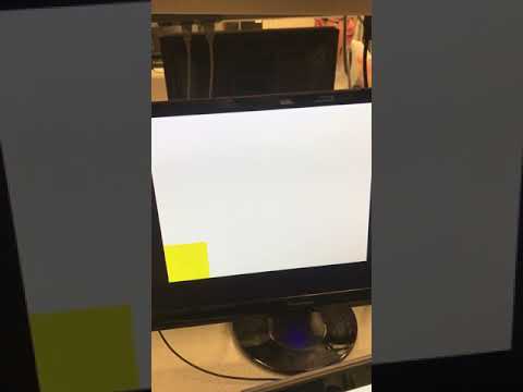
Here’s a video of the program in operation (the yellow tile shows the current location, grey tiles are unexplored, and white tiles are explored):
Results: Merged Code
Finally, both teams came together to transmit information from the robot’s Arduino to the base station Arduino, which then stores the state of the maze in memory and relays this information to the FPGA via a custom half-duplex SPI protocol running at about 1MHz, that we developed in the last two labs. The transmitter code shown below integrates the maze traversal simulation code that the FPGA team worked on. It traverses the maze in a snaking pattern, transmitting only the new data about the current tile it is on.
Robot Arduino (transmitter):
    // First, stop listening so we can talk.
    radio.stopListening();

    unsigned int new_data;

    // Traversal algorithm
    unsigned char traverse = 1;
    unsigned char current = 1;
    if (turn == 0) x_coord++;
    if (turn == 1) x_coord--;
    if (x_coord > X_SIZE - 1){
      turn = 1;
      y_coord++;
      x_coord--;
    }
    if (x_coord < 0) {
      turn = 0;
      y_coord++;
      x_coord++;
    }
    if (y_coord > Y_SIZE - 1) y_coord = 0;

    // Use bit shifting to pack the bits
    // For deployment with a robot, something like this should be factored out into
    // a function, along with the code to unpack the bits
    new_data = x_coord << 13 | y_coord << 11 | traverse << 2 | current << 1;

    // For the test case of (5, 5, 3) the byte shoud look like: 10010011
    // In decimal this is 147

    // Take the time, and send it.  This will block until complete
    printf("Now sending new map data\n");
    bool ok = radio.write( &new_data, sizeof(new_data) );

    if (ok)
      printf("ok...");
    else {
      printf("failed.\n\r");
      while(!ok){
         ok = radio.write( &new_data, sizeof(new_data) );
      }
      printf("ok...");
    }

    // Now, continue listening
    radio.startListening();
On the base station side, we receive the new maze data from the robot Arduino. Since power is less of a concern for the base station Arduino, it stores the entire maze array in the integer array “maze”, updates it with new data received over RF, and sends the entire maze array to the FPGA over SPI to display on the VGA monitor.
Base Station Arduino (receiver):
      // First, stop listening so we can talk
      radio.stopListening();
      SPI.beginTransaction(SPISettings(1000000, MSBFIRST, SPI_MODE0)); //10MHz
      unsigned int result = got_data;
      unsigned char got_x = (got_data >> 13);
      unsigned char got_y = (got_data >> 11) & 0x3;
      maze[got_x][got_y] = got_data;
      for (uint16_t x = 0; x < X_SIZE; x++) {
        for (uint16_t y = 0; y < Y_SIZE; y++) {
          if ((x != got_x) && (y != got_y)) maze[x][y] = maze[x][y] & 0xfffd;
          digitalWrite(7, LOW);
          SPI.transfer16(maze[x][y]);
          digitalWrite(7, HIGH);
        }
      }

  SPI.endTransaction();
      // Send the final one back.
      radio.write( &got_data, sizeof(got_data) );
      printf("Sent response.\n\r");

      // Now, resume listening so we catch the next packets.
      radio.startListening();
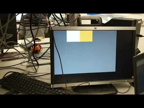
Our efforts resulted in the wireless transmission of a simulated maze exploration (preprogrammed path, snakes its way down the maze) shown in the video below:
Handling Dropped Packets
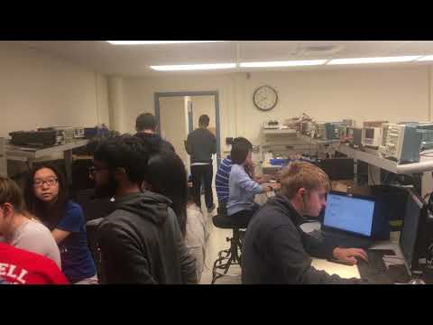
We were also able to gracefully handle dropped packets by utilizing the auto-acknowledgment feature of the RF module. As shown in the snippet below, if the transmitter does not receive an acknowledgment that the packet has been received, it stays in a while loop, resending the packet until it successfully sends. This check prevents the situation where a dropped packet would cause a misalignment in the base station’s maze array. In the video below, you can see Norman Chen holding the robot with the transmitter attached. The transmitter is also generating a fake maze exploration. Norman walks too far away from the base station, and you can see that the maze stops updating. Then, he walks closer and the maze resumes updating where it left off, gracefully handling dropped packets.
    // Take the time, and send it.  This will block until complete
    printf("Now sending new map data\n");
    bool ok = radio.write( &new_data, sizeof(new_data) );

    if (ok)
      printf("ok...");
    else {
      printf("failed.\n\r");
      while(!ok){
         ok = radio.write( &new_data, sizeof(new_data) );
      }
      printf("ok...");
    }
Conclusion
Our team was able to successfully complete both tasks in Lab 4. We created a successful communication protocol that encompasses all the information needed for the final maze. The radio team successfully used the RF transceivers to establish wireless communication between our robot and base station. By the end of the lab we simulated the robot navigating the maze in an S-formation. The robot’s Arduino then transmits its current location to the case station which indicates on the grid the current status.
Completing these two tasks was good practice with using the DE0-Nano Development Board and the Nordic nRF24L01+ transceivers. This lab encouraged us to hash out the final details for our base station and gave us a good start on implementing the final system.